Gamecube Controller Wiring Diagram
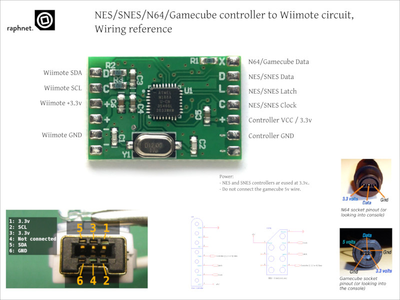
Wiring diagram for an external and internal arduino setup for a gamecube controller, along with code to read inputs from the controller and map them to macros to send. Nes/snes/n64/gamecube controller to wiimote circuit a small circuit to connect a nes, snes, n64 or gamecube controller to a wiimote.

[VF_6280] Gamecube Controller Diagram Download Diagram
N64 controller expansion slot behavior.

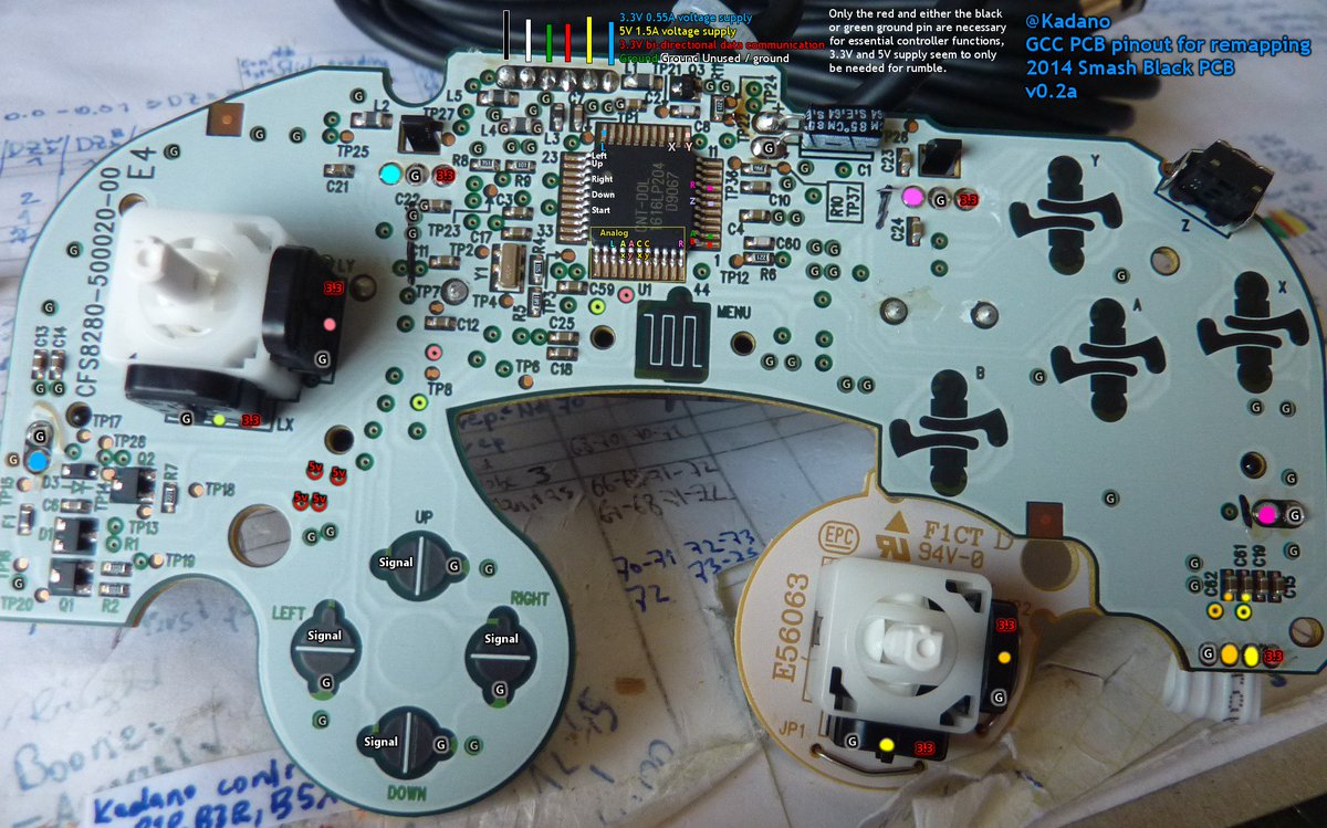
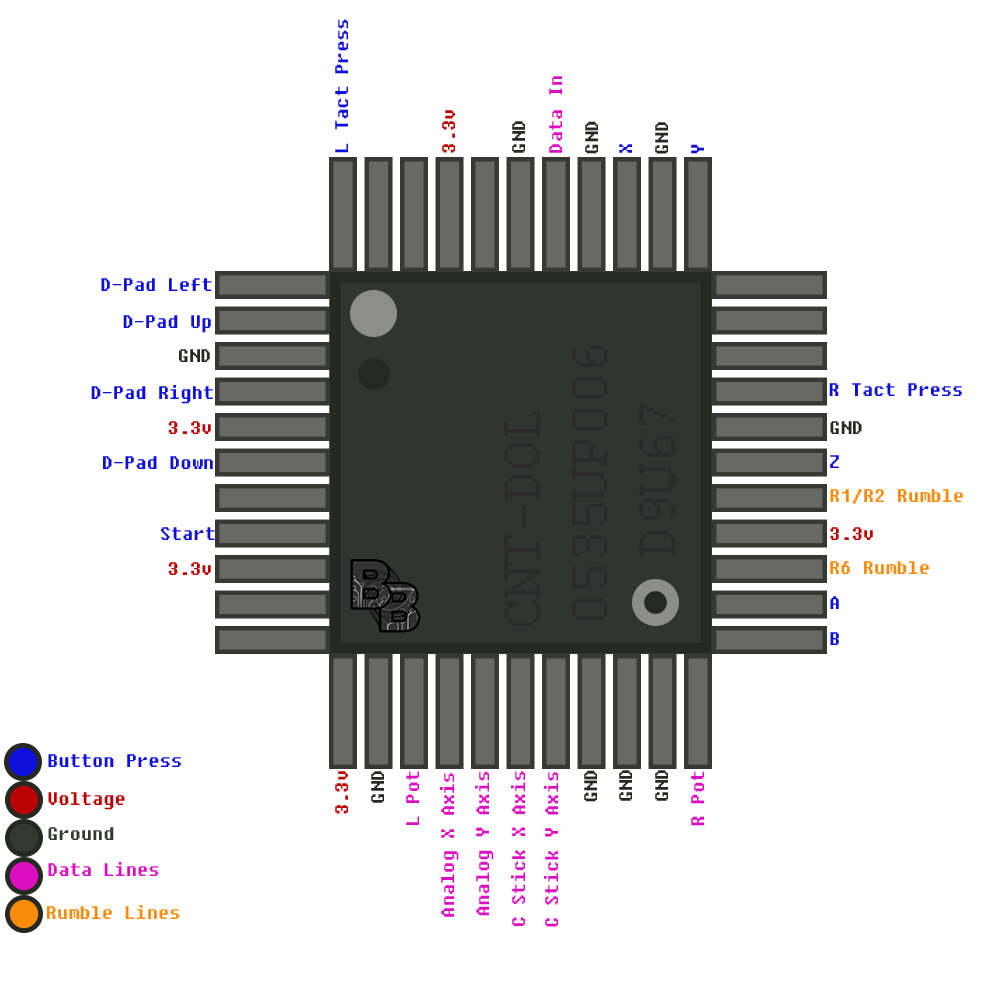
Gamecube controller wiring diagram. It doesn't feel like wire to me, also there's a bunch of white padding in the middle, i'm not quite sure what that's for. Com mart home depot landscape lighting transformer info via martgeto. Here is a wiring diagram for the board:
On the gamecube side, the data signal is held at 3.43 volts via a pullup resistor inside the gamecube. Some stuff i'm unsure about: Nintendo gamecube controller connector pinout.
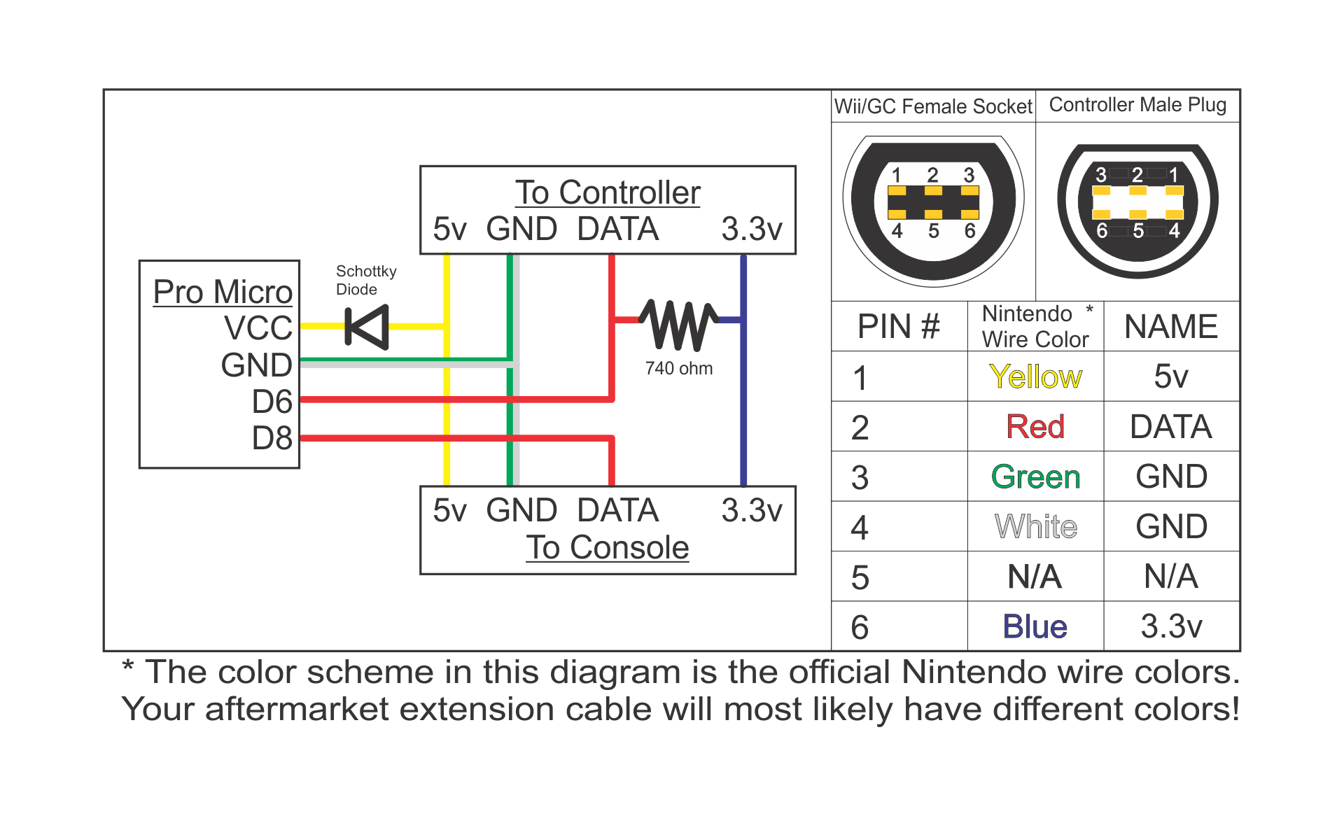
3.2) n64 and gamecube controller pinout due to the high number of different controller and extension brands which use varying color schemes, i cannot provide an universal wiring diagram based on wire colors. On the pin labeled 1 (second pin on the top row of pins on ra1) is p1 data. The simple goal in wiring is to have the grounds and signals of each device linked to the ground and desired corresponding signals on the pcb.
The official nintendo controller only seems to wire 5/6 of these pins, and of those only one seems to be used for data transfer between the console and the controller. Many games assume an axis to be active when the value it reads is different, within a certain margin, from the center position. The safest way to find out how.
Gc>midi has three modes, a drum mode, a synth mode, and a mode specifically for the donkey konga bongo controller. The gamecube controller sliders are often problematic because they lack a central resting position. Wiring diagram nintendo 64 controller entertainment system png 1300x700px area electrical wires cable game.
If you like it please feel free to a small amount of money to secure the future of this website. Make your own bluecubemod added firmware pcb files battery design details hackaday io. Can be installed inside a controller for a permanent conversion or used to build a custom adapter.
In addition, due to the popularity of the gamecube controller, there are many adapters on the market that would allow this controller to also be used for pc, playstation, or xbox games. By admin | december 9, 2017. Fe 5603 gamecube controller wiring diagram right stick schematic wiring.
The cost of running this website is covered by advertisements. Well, on the definitive wii trimming guide , in the gamecube controller section where you can see ra1, you will notice numbers on the pin. When someone (gamecube or controller) wishes to set the signal to 0, it just has to pull the signal to ground.
The white 2008 controller introduced a longer. Gamecube controller protocol¶ the gamecube controller uses 3.3v logic (bidirectional), 3.3v to power the controller, and 5v for the rumble motor. 3.3v 0.55a voltage supply 5v 1.5a voltage supply 3.3v data data ground white is power ground (rumble) ground up until 2008, all the cables were black and 2m (6.5ft) long.
I acheive this by playing with the atmega8 pin direction. Hd wii nunchuck wiring diagram pl7602 remote schematics protel u up component full nintendo diagrams ct 9344 av multi pinout nfg games gamesx guitar hero xbox 360 controller palotakentang playstation 4 switch 64 the inside out top 1998 evinrude 150 microcontroller gamecube digital whiteboard with ir charvel active humbucker wire. Gamecube to nintendo 64 controller converter by.
The wiring for every generic n64 controller i've found thus far. Here’s a few schematics of the wiring: Go to the section labeled schematics and you have a circuit diagram.
Wiring diagram for an external and internal arduino setup for a gamecube controller, along with code to read inputs from the controller and map them to macros to send to the console. The nintendo 64 controller wire wrap according the diagram on the right.n64 controller wiring diagram ~ here you are at our site, this is images about n64 controller wiring diagram posted by alice ferreira in diagram category on nov 12, you can also find other images like wiring diagram, parts diagram, replacement parts. And finally, here are the gerber files which you can use produce this pcb:
Figure converter design block diagram. The 5v power used by the rumble motor is always on, and the motor is controlled by a command sent to the controller. Now also compatible with the nes and snes classic editions.
I'm trying to splice back together a gamecube controller wire, there are five wires to connect but i don't know what coppery stuff is, does that need soldering? The other p[x] data pins i. 1.2 solution overview macrome is a programmable controller that looks like a standard gamecube controller visually, but with additional features.
Gamecube controller pinout issue 4 ezhid firmware looping a signal with wires project bluetooth mod kit nes snes n64 to pcb guide breakout box external arduino raphnet homepage mbed wii 1st party usb adapter connect additional controllers. Wiring database 2020 28 gamecube controller diagram. A pcb from another source can be used in replacing the electronics in a standard device, or giving communications to a custom controller.
It appears that you are using adblocking software.
30 Gamecube Controller Diagram Free Wiring Diagram Source
N64/Gamecube controller to USB adapter

NES/SNES/N64/Gamecube controller to Wiimote circuit
30 Gamecube Controller Diagram Free Wiring Diagram Source
Gamecube Controller Diagram General Wiring Diagram

Gamecube Controller Diagram Diagram Resource Gallery

32 Gamecube Controller Diagram Wiring Diagram Database
28 Gamecube Controller Diagram Wiring Database 2020
Gamecube Controller Diagram Diagram Resource Gallery
30 Gamecube Controller Diagram Free Wiring Diagram Source

Gamecube wiring! consolerepair

Gamecube Controller Diagram General Wiring Diagram
technologies Gamecube controller to N64 circuit
technologies NES/SNES/N64/Gamecube controller to Wiimote circuit
28 Gamecube Controller Diagram Wiring Database 2020
N64/Gamecube controller to USB adapter

28 Gamecube Controller Diagram Wiring Database 2020

Gamecube Controller Diagram General Wiring Diagram

GitHub Skuzee/ESSAdapter An adapter to make Gamecube controllers feel more like n64


