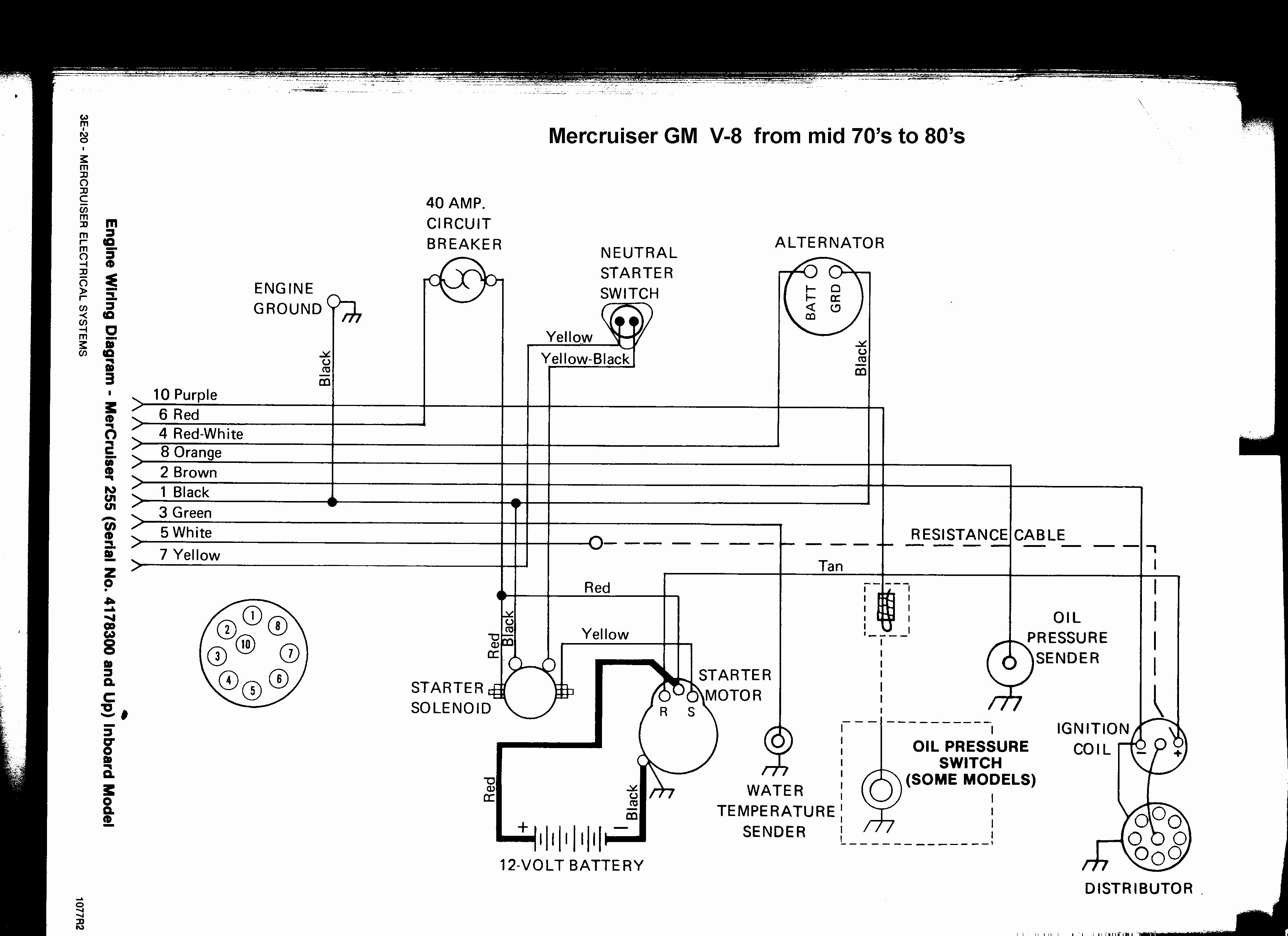
Quicksilver Wiring Diagram
It stands for the physical parts of the electric circuit as geometrical shapes, with the actual power and also link connections between them as thin edges. Reference numbers in this diagram can be found in a light blue row below — scroll down to order.

1980 Mercury 80hp Wiring Diagram
Sometimes the wires will cross.
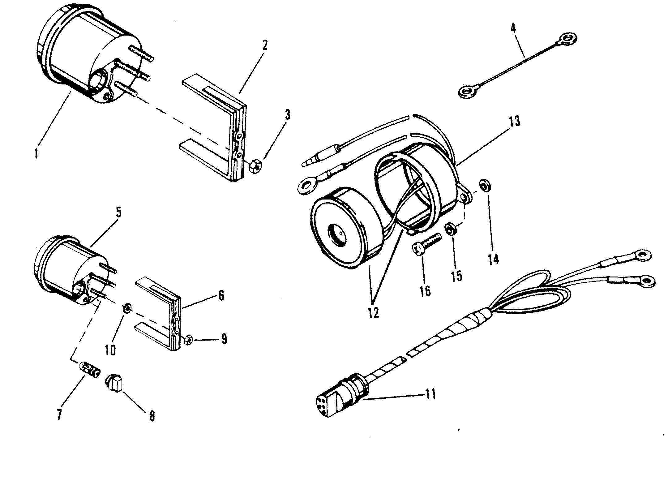
Quicksilver wiring diagram. Wiring diagram not just gives comprehensive illustrations of what you can perform, but in addition the procedures you need to follow although performing so. 800 x 600 px, source: 3 0 mercruiser ignition coil wiring diagram by yahutt mang december 15 2018 1994 ford probe diagram wiring diagram1995 box mercruiser 3 0 diagram 1 smo zionsnowboards de u2022 rh electrical system wiring diagrams.
Quicksilver disassembly/ trim switch hi this is how you take off the handle to get to the switch and wires. Mercruiser fuel pump wiring diagram wiring diagram is a simplified pleasing pictorial representation of an electrical circuitit shows the components of the circuit as simplified shapes and the facility and signal contacts along with the devices. (advanced throttle only) (a21 and a41).
Question, does the switch in question have a push feature? I have a quicksilver series throttle that has an up and down trim and i'll send you a typical wiring diagram for a mercruiser trim system. Oleh anonim maret 11, 2020 posting komentar.
Sold mercruiser quicksilver shifter control handle flush sold mercruiser quicksilver throttle shift control box assy sold mercruiser quicksilver throttle shift control box assy mercruiser 4 cyl 3 0 service manual gasoline internal quicksilver commander. 1990 4.3 wiring diagram april 24th, 2011, 07:40 pm changed motors due to a cracked. 4e 0 wiring diagrams 90 816462 2 695 table of contents page.
Mercury marine remote controls and components modular components parts. Wiring diagram april 14, 2020 05:32. Diagram of the “down” circuit.
Mercruiser inboard engine ignition wiring diagram keywords: Mercruiser ignition wiring diagram collections of mercruiser 5 7 wiring diagram collection. Connect wires together with screw and hex nut.
It is meant to assist all of the typical consumer in building a correct method. Shorts out the ignition modules when you turn the key off. Each component ought to be placed and connected with different parts in particular way.
I have a quicksilver series throttle that has an up and down trim and i'll send you a typical wiring diagram for a mercruiser trim system. Apply quicksilver liquid neoprene to connection and slide rubber sleeve over connection. Each product #9, a 1, throttle lever assembly (1 required per assembly).
The linked images are printable but may print across more than 1 page (in order to be legible). Buy a genuine mercury quicksilver or aftermarket part. If not, the arrangement will not work as it should be.
Mercruiser trim sender wiring diagram. Mercruiser trim solenoid diagram you are. Mercruiser 5 7 wiring diagram wiring diagrams thumbs mercruiser 57 wiring diagram in addition wiring diagram gives you the time frame by which the projects are for being finished.
Yes, tan (light brown) is for the warning horn (grounds at the engine to activate). Power for a second fused accessory panel may be tasken from this connection. Wiring diagram will come with a number of easy to stick to wiring diagram directions.
Or you are a student, or maybe even you that simply wish to know about mercruiser 350 wiring diagram. Mercruiser trim pump wiring wiring diagram wire diagram electrical diagram source. Mercury outboard wiring diagram thread trouble starting it shows the parts of the circuit as streamlined forms, and the power […]
With this kind of an illustrative guidebook, you will be capable of troubleshoot,. It shows the components of the circuit as simplified shapes, and the. Quicksilver 3000 wiring diagram may 29, · re:
Changed by the previous owner so the wires may not be correct but have voltage to the switch it is a three wire motor the 2 small terminals on solenoid one blue wire from the switch. B starting charging and choke components 1 alternator 2 electric choke 3 ground stud 4 starter motor 5 starter slave solenoid. Mercruiser 4.3 wiring diagram.variety of mercruiser ignition wiring diagram.
These directions will probably be easy to grasp and use. [ebook] quicksilver series trim control wiring diagram pdf books this is the book you are looking for, from the many other titlesof quicksilver table of contents. To remove the handle shift the control backwards to about 1/4 to 1/2 position this will enable you to popout the push button for nuetral.
B starting charging and choke components 1 alternator 2 electric choke 3 ground stud 4 starter motor 5 starter slave solenoid. Or handle, a pump motor and a trim limit switch,. Each part ought to be set and linked to different parts in specific way.
Behind that button is a bolt remove it and the handle. Quicksilver throttle control wiring diagram. Quicksilver control box wiring color codes and yellow/black engine shut down.
When the pump operates in the downward mode. Quicksilver ignition switch wiring diagram mercury ignition switch wiring diagram 120xr oil injection motor. Otherwise, the arrangement will not function as it should be.
A ignition components 1 distributor 2 ignition coil 3 shift cutout switch. Initially, quicksilver was engaged in the sale of spare parts and accessories for mercury marine in the european region, but in 1991 it was decided to reorient the.
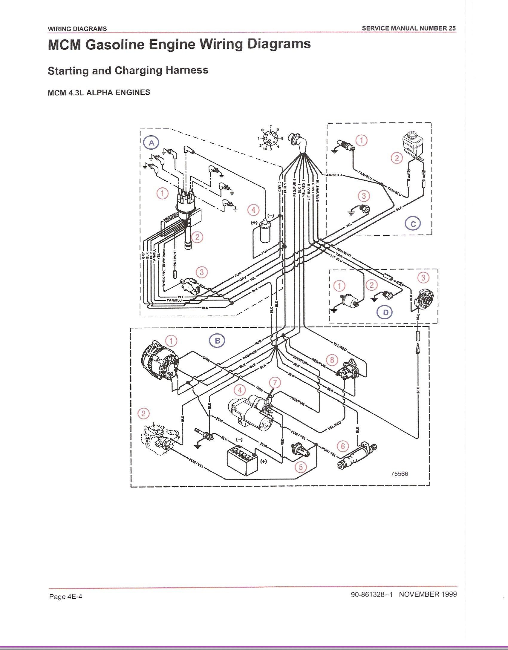
Mercruiser Ignition Wiring Diagram Cadician's Blog
Quicksilver Trim Switch Wiring Diagram
I have a 1980's Mercury 200hp outboard. Only have spark on one side and intermit spark on the
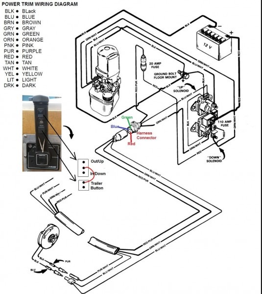
13+ Wiring Diagram For Quicksilver Control Box Images alborozmaryory

mercruiser 5.7 starter wiring question Bloodydecks
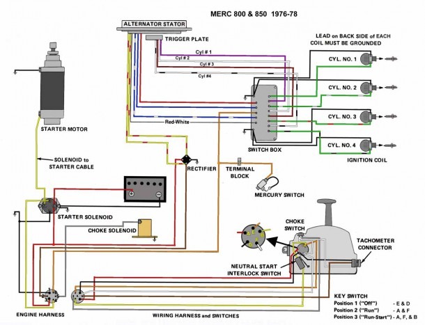
Quicksilver 3000 Parts Diagram

Wiring Diagram for Mercury Outboard Motor Sample

Quicksilver 3000 Wiring Diagram

I have a 1979 Glastron ssv177 xl. It has a 140 mercruiser inboard. I replaced the ignition

Mercruiser Theunderbolt 4 Wiring Diagram
Quicksilver 3000 Wiring Diagram
Quicksilver 3000 Wiring Diagram
Mercury Outboard Starter Solenoid Wiring Diagram MSTYLEANDYOUMSAY

Quicksilver Trim Switch Wiring Diagram
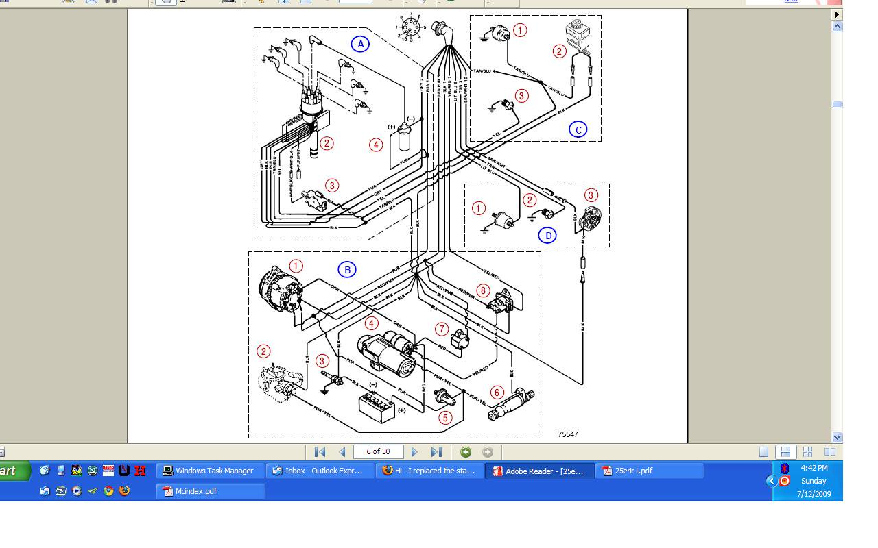
Mercruiser Ignition Coil Wiring Diagram Today Wiring Diagram Mercruiser 4.3 Wiring Diagram

16+ Mercruiser 140 Engine Wiring Diagram Engine Diagram in 2020 Electrical
Quicksilver Commander 2000 Wiring Diagram Wiring Diagram


