Minimize Noise In Audio Channels With Mixed Signal Pcb Layout
After some investigation it came from the power supply. It minimizes noise pickup and the board area required.

TheRandomLab Simple passive mono/stereo to stereo audio
Here is a summary of the general rules to laying out a mixed signal pcb:
Minimize noise in audio channels with mixed signal pcb layout. The first focuses on reducing the switching noise generated in digital clock buffers. When i completely separated the grounds and joined them once at the edge connector all the hum disappeared. Minimize noise in audio channels with smart pcb layout
Adc noise reduction in your analog pcb signal chain by zm peterson • Pic microcontroller and reducing noise. This article explains how to minimize noise in systems consisting of multiple subsystems through careful component layout and attention to grounding.
2 while designing the pcb layout, keep the signal traces as thin and as small as possible. Reducing input noise from pulsed current from buck reg: I had simply mixed the audio and power supply grounds willy nilly.
For signal traces you also need to keep those as short as possible, except for. Analogue and mixed signal audio are often neglected. I am now going to design a pcb, but first i want to know what i could change in the circuit to further reduce noise.
Even the best designers often have to build more than 1 pcb to produce a high quality noise free design. Use board vias if required to keep the traces small. This task is called floor planning. careful component placement can ease signal routing and ground partitioning.
The circuit works on a solderless breadboard with acceptable but still quite noticable noise. Component placement the first step of any pcb design is choosing where to place the components. Audio mixers can be analog or digital type.
Substrate noise received in an analog circuit degrades the performance of the circuit. The first step of any pcb design is choosing where to place the components. Need tips for reducing emi, circuit picking up +700mv noise from high bay lights.
• make sure that digital components and analog components are assigned to their respective partitions. I am working on an audio circuit featuring the mos technology 6581 sid. From a certain perspective, previous generations of electronics were rather forgiving and design errors would still allow you to create a functional board.
This keeps their inductance low and helps to control the noise. A solid ground plane next to the power plane creates a set of low equivalent series resistances (esr. In general, the shorter and fatter you can make your power traces, the better.
Mixed signal pcb design techniques the analog world in which we live is constantly being captured in one way or another, and the media is being shared globally. Reducing noise in an audio. Proper printed circuit board (pcb) layout techniques.
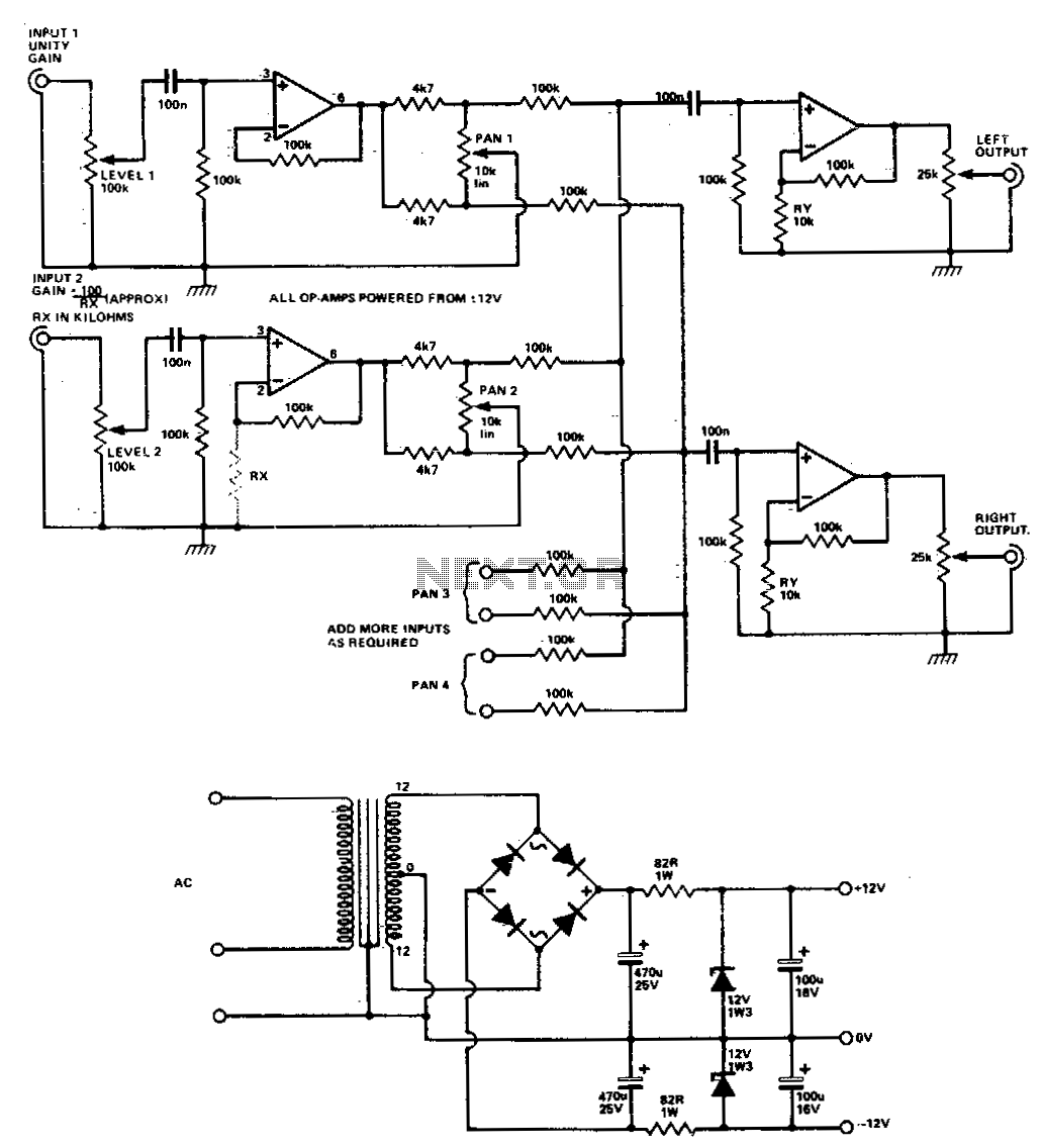
An audio mixer, also called a mixing console, is an electronic device for combining, and modifying audio signals.the modified audio signals are summed to produce some combined output signals. Traces that are less than 8 millimeters thick are generally considered good at reducing. If the noise goes away then you can assume that the problem is either with the signal level on the input, or that you're asking the amp to put out more than the rated 3.5 watts.
Either using the control on the electronic piano or by using the pot in your circuit. This is what i considered: Learn what ground bounce is and how you can avoid it with design decisions from pcb layout to programming.
• begin by defining the analog and digital portions of your design. Pcb design is not taught to most undergraduate engineers. Circuitry is often given the least consideration during pcb design.
This short seminar revisits many design considerations often neglected or overlooked in striving to achieve optimum audio performance and reduction of emc and digital interaction. Normally to cover the important aspects of good analogue and mixed signal pcb design would take at least a couple. • partition your pcb into an analog and a digital portion.
This task is called floor planning. careful component placement can ease signal routing and ground partitioning. / geek area / electronics / audio / audio circuit and pcb design tips designing audio circuits remains a challenge and aspects of it are still often considered a bit of a black art. It minimizes noise pickup and the board area required.
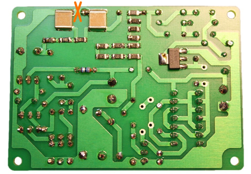
It provides a practical approach rather than a theoretical discussion. I fell flat on my face with a audio mixer pcb when there was hum everywhere getting into the audio stream. In between the creation and consumption of all of this data, the information is converted to digital representations of itself for storage and transmission.
Two new noise reduction methods are proposed in this thesis work.
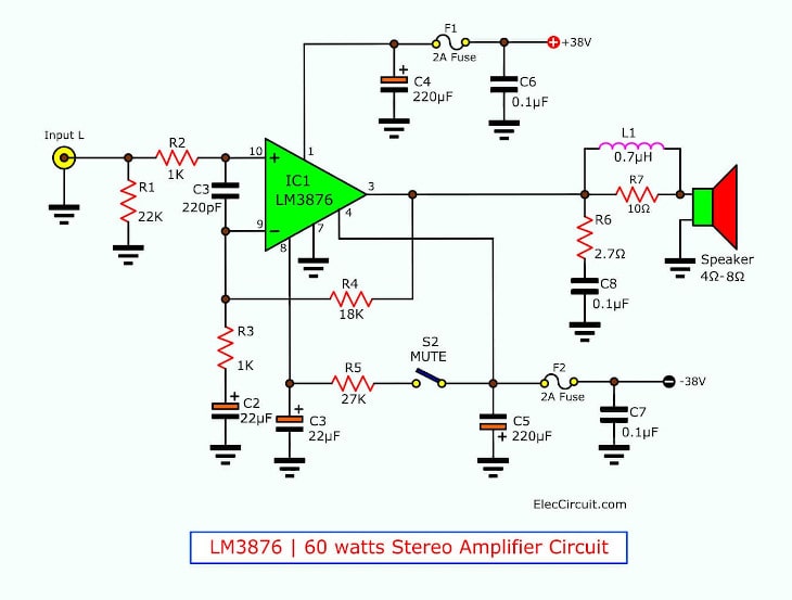
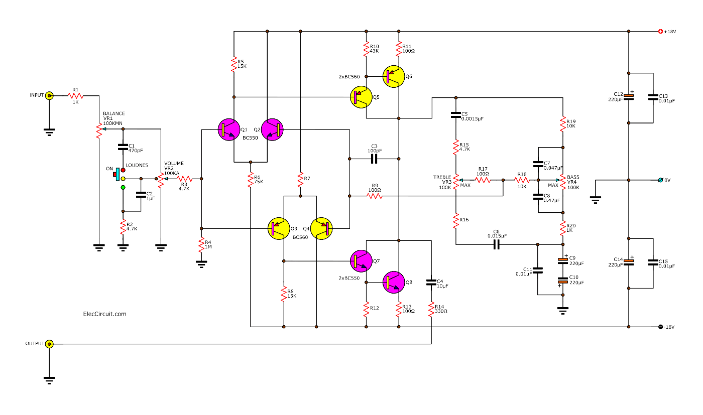
60 watt stereo amplifier circuit without customization
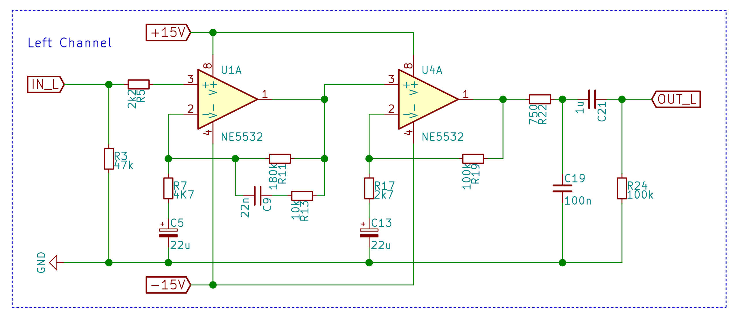
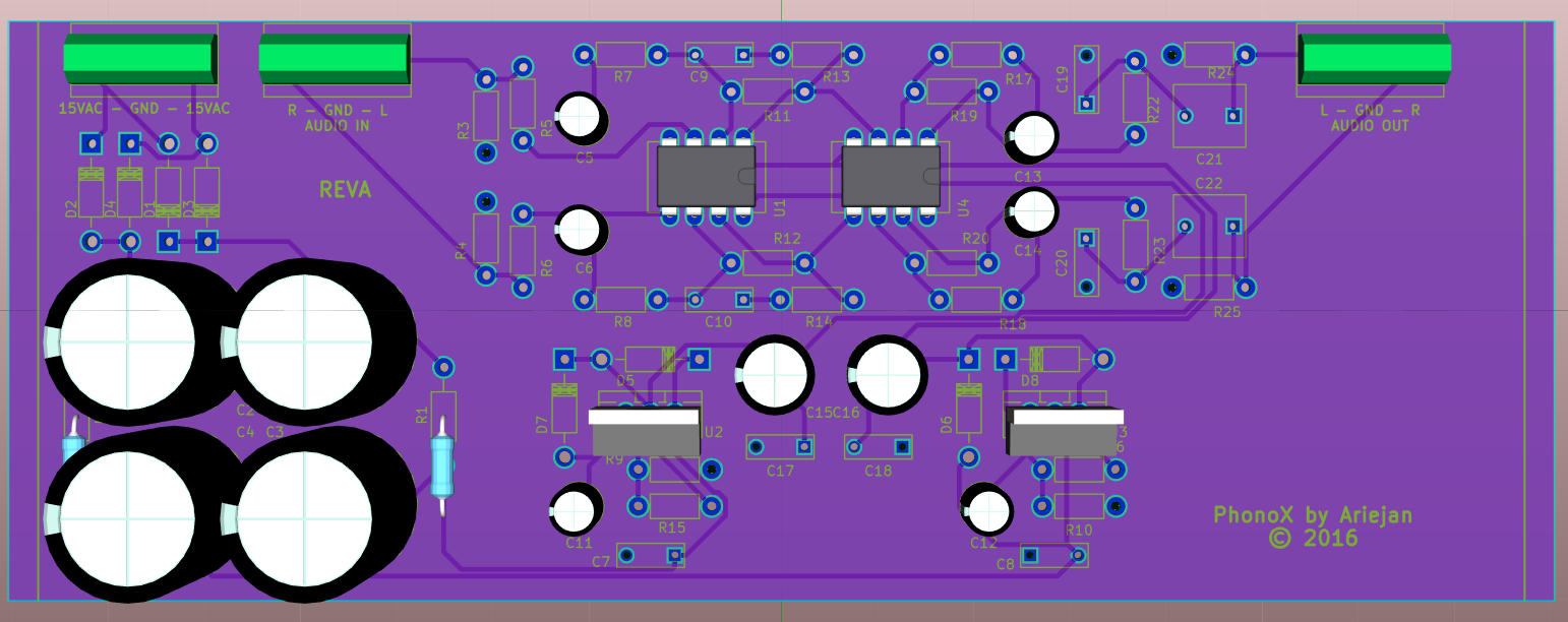
Design Phono X, a RIAA Phono Preamplifier · devroom.io
Super digital echo stereo mixer circuit projects
Design Phono X, a RIAA Phono Preamplifier · devroom.io

voltage regulator Reducing noise in mixedsignal audio

TheRandomLab Simple passive mono/stereo to stereo audio

TDA2030 make for Subwoofer Amplifier Circuit Electronic
Digital Ground And Analog Ground Circuit Circuit Boards

Low Frequency Frequency Modulated Sound Card Capture


Audio mixer circuit diagram pdf

voltage regulator Reducing noise in mixedsignal audio

315 Watt Class D Power Amplifier Amplifier Circuit Design

Schematic October 2014
Ground Loops In Pcb PCB Designs
A 5channel mixer / preamplifier for piezo disks by

Super digital echo stereo mixer circuit projects
audio mixer circuit Audio Circuits Next.gr

10 Channel Equalizer using 4558 IC Electronic Circuit

DIY JFET Mic Pre DIY JFET Mic Preamp and Beyond! Tape